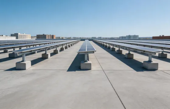
Commercial Flat Roofs
Ballast trays, low-tilt frames, wind-edge zones, and access paths are considered together so the quotation supports both engineering review and installation staging.
The same catalog can behave differently by site type. Mounting Systems keeps application guidance tied to the physical interface, installation sequence, and packing plan.
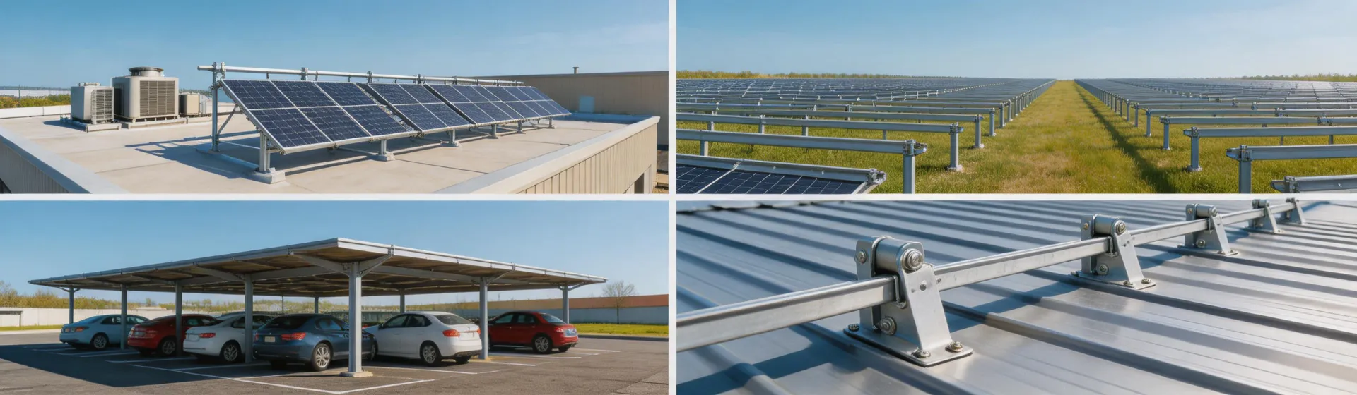
Application review begins with the surface that carries the array. A commercial roof project may be controlled by ballast limits and access paths. A utility ground array may be controlled by post spacing, row repetition, and installation speed. A carport may be controlled by steel coordination, drainage, and clearances. Treating these projects as one generic product category creates confusion, so each application is described by the work that must happen before hardware leaves the warehouse.
Ballast trays, low-tilt frames, wind-edge zones, and access paths are considered together so the quotation supports both engineering review and installation staging.

Post spacing, table configuration, row labels, soil assumptions, and container packing are arranged for repeatable field work across large blocks.
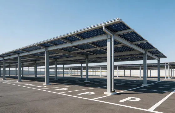
Steel support, module attachment, drainage direction, and access clearance need a more coordinated review than a standard roof kit.
For each application, Mounting Systems can help translate a product request into a practical package. That may include identifying whether clamps or flashed attachments are appropriate, whether a ballast layout needs additional review, whether module frame dimensions match the intended clamp zone, or whether ground rows should be grouped by table for easier field staging. The goal is to reduce uncertainty without pretending that every site condition can be solved from a catalog line alone.
Ground-mount projects can be specified with fixed-tilt structures or single-axis trackers. The right answer depends on land cost, irradiance profile, O&M expectations, and project IRR. We document both paths so EPCs and asset owners can compare on the same engineering criteria.
Lower capex, no moving parts, simpler O&M, and shorter construction time. Ideal for high-irradiance regions, smaller projects, and sites where land is not the binding constraint. ASCE 7 wind-load documentation is straightforward.
Energy yield gains of 15-25% in many latitudes, better LCOE on utility projects with stable irradiance. Requires a tracker control system and a more demanding maintenance plan. Tilt range typically up to plus/minus 60 degrees.
Mounting Systems can provide structural calculation packages, wind-tunnel summaries, and bonding/grounding documentation so the structure decision is auditable for lender review.
Send the application context before the order is locked. Early review can prevent the wrong attachment, the wrong accessory count, or an inefficient packing plan from reaching the crew.